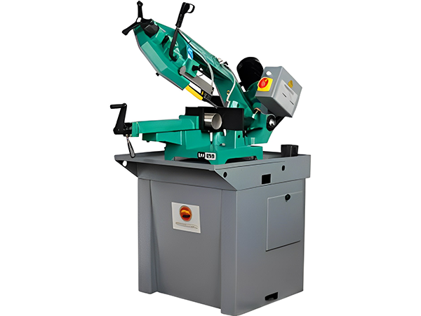
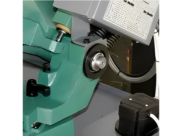
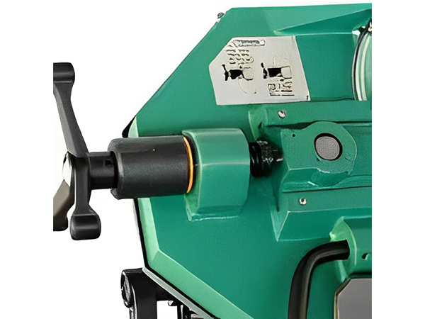
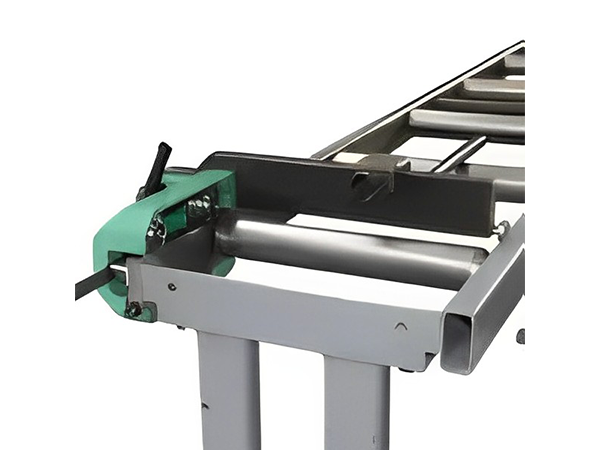
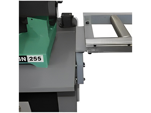
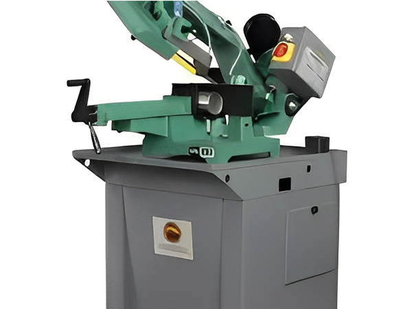
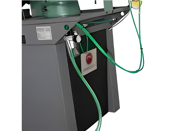
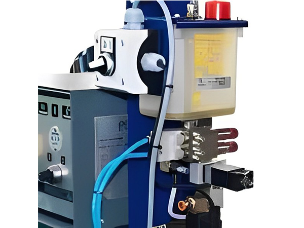
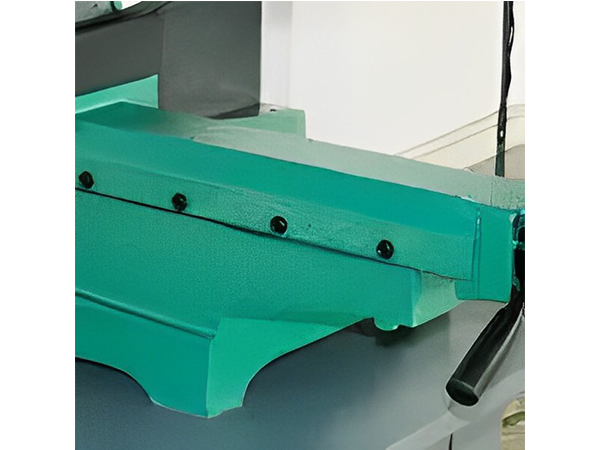
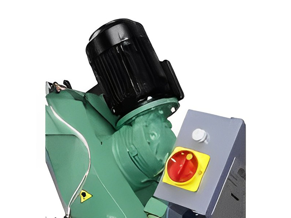
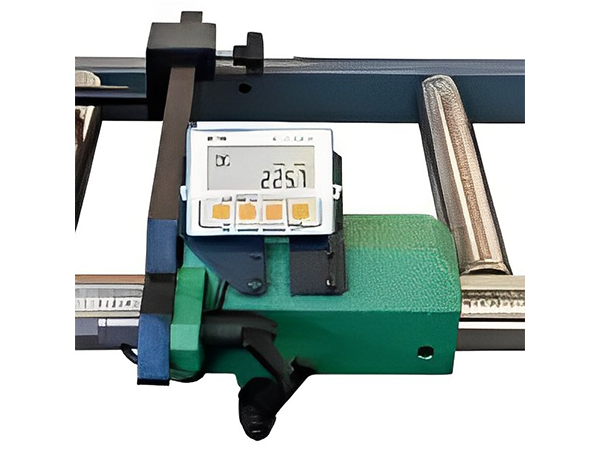
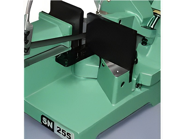
"**KEY ELEMENTS:**\n\n* All main structural components (bow \u2013 vice \u2013 machine base) are in cast iron.\n* Monolithic bow can rotate together with support plate.\n* Tube support plate grooved for band-saw seat.\n* Extraordinary cutting capacity.\n* Band-saw dimension 2.500x19x0.9 mm\nCutting field: 0\u00b0 \u2013 60\u00b0 L\nCut capacity at 0\u00b0 = 220 mm\n\n**BOW AND FIELD OF CUT:**\n\n* The BROWN SN 255 MRM offers a field of cut from 0 to 60\u00b0 with SX peg reference: the headband wheel solid with the support surface allowing the saw blade to finish the cut always within the groove formed on it: the ground plane is never affected.\n* Binaural monolithic cast iron flywheels are keyed in which that support ribbon cutting is hinged and pivoting on bearings.\n* Double balancing springs on bow and eccentric bush for the regulation of orthogonality.\n* The inclination of the bow (40\u00b0), the tape length (2500 mm) and the diameter of wheels (320 mm), were studied in order to limit the yield strength of the tape, thus increasing its duration.\n* The placement of the bow is adjustable by mechanical stops to cut at 0\u00b0, 45\u00b0 and 60\u00b0 left.\n* The tape is supported by two guides blade guides that accompany the flow through the blade carbide tipped TCT adjustable.\u00a0Adjustable blade guide arm according to the size of the workpiece.\n* Lubricating and cooling system with electric pump belt and two adjustable taps placed on the blade guides: the emulsifier mixture is released automatically every time you press the start cycle start.\n* A tensioning device of the mechanical spring through bandsaw blade: ideal solution to ensure uniformity and consistency in the tension of the tape.\u00a0Precision slide with oilers.\n* Start Button Ribbon \u201cman\u201d.\u00a0It allows you to start the rotation of the tape at a speed previously selected and is protected by a jumper against accidental operation.\n\n**ENGINE CONTROL PANEL:**\n\n* Three-phase motor with two speeds in the upright position to reduce clutter back.\n* Reducing the number of revolutions of the motor is obtained by a screw \/ ring reducer with a ratio of 1:49.\n* Control panel located in an easily accessible button on \/ off switch of the machine and the cutting speed.\n\n**AND BASE MACHINE VICE CLAMPING PIECE:**\n\n* Machine base in cast iron with ground plane rotating solid steel pieces with a bow and grooved seat belt.\u00a0The support surface supports the workpiece even in the crosscuts avoiding to affect the base.\n* Mechanical stops recorded at 0, \u00a045\u00b0 and 60\u00b0 to the left \u2013 the latch levers for intermediate degrees.\n* Graduated line engraved easy, easy reading, from 0 to 60\u00b0.\n* Adjustable mechanical vice.\u00a0It consists of the gradual approach to the crank, pull and lock the workpiece in the vice and adjustable gib plate with grains.\n* Welded sheet metal basin with integrated coolant tank and pump out for the cleaning of the tank.\n* Pedestal made of sheet steel modular.\n\n**PARTS ADJUSTABLE SAFETY SYSTEMS:**\n\n* Adjustable machine parts: mechanical stops at 0\u00b0, 45\u00b0, 60\u00b0 LEFT, vice assembly, support group bow, perpendicular horizontal and vertical bow.\n* Security guards: micro switch on the crankcase cover flywheels that stops the engine immediately when opened, guards on the part of the blade is not involved in cutting, start button tape rotation \u201cman\u201d protected against accidental operation, lockable main switch, low voltage controls.\n\n**OPERATION:**\n\nMachine operation manual handling (downhill and uphill) of the bow and the movement of the vise clamping piece (opening and closing) must be performed manually by the operator.\n\nPutting the machine live at the main switch located on the control panel and then select the most appropriate cutting speed for the material and the section to be cut.\nThen:\n* Manual closing of the clamp;\n* Start button to start the tape rotation \u201cman\u201d;\n* Manual lowering of the bow;\n* Implementation of cutting;\n* Manual return to the initial position of the bow;\n* Releasing the button \u201cman\u201d with stopping the rotation of the tape;\n* Manual opening by the clamp lever for quick approach;\n* Placement of the next workpiece.\n\n**TECHNICAL SPECS:**\n\n| **CUTTING CAPACITY** | | | | | |\n| --- | --- | --- | --- | --- | --- |\n| | | **45\u00b0 DX** | **0\u00b0** | **45\u00b0 LEFT** | **60\u00b0 LEFT** |\n| --- | --- | --- | --- | --- | --- |\n| ROUND | mm | \u2013 | 220 | 160 | 90 |\n| FRAMEWORK | mm | \u2013 | 220 | 120 | 60 |\n| RECTANGLE | mm | \u2013 | 230 x 200 | 160 x 140 | 100 x 60 |\n\n| **SPECIFICATIONS** | | |\n| --- | --- | --- |\n| Three-phase motor rotation tape | kW | 0.75 \/ 1.1 |\n| Reduction unit in oil bath | | 1:49 |\n| Size flywheels \u00d8 | mm | 320 |\n| Development bandsaw blade as standard | mm | 2500 x 19 x 0.9 |\n| Cutting Thickness | mm | 1.0 |\n| Max opening vise clamp | mm | 230 |\n| Cutting speed | m \/ min | 35\/70 |\n| Tension band saw blade | kg | 600 |\n| Bow angle | | 40 \u00b0 |\n| Cutting range | | 0-60 \u00b0 LEFT |\n| Electric | kW | 12:10 |\n| Coolant tank capacity | lt | 14 |\n| Height of working | mm | 940 |\n| Max size of the machine | mm | 730 x 1,870 x 1,500 |\n| Weight | kg | 275 |\n\n**VERSIONS:**\n\n* BROWN SN 255 MRM (with grip rapid manual) \n Single-phase version (V 230-50 Hz) \u2013 1 tape rotation speed.\n* BROWN SN 255 MRM (with grip rapid manual) \n Three-phase version (V 230 \u2013 50 Hz or 400 V \u2013 50 Hz) \u2013 2 tape rotation speed.\n\nOn request, you can get voltages and \/ or frequencies are different from those mentioned above.\n\n**OPTIONS:**\n\n* Metal band saw blade.\n* Coolant.\n* Loading roller conveyor 1000 mm.\n* Loading roller conveyor 2000 mm.\n* Extension roller load in modules of 2000 mm.\n* Bar stop with manual unloading roller 2000 mm.\n* Extension unloading roller, in modules of 2000 mm.\n* Digital Display Kit for unloading roller.\n* Group nebulizer.\n* Kit pneumatic clamp (MRP)."
(Image shows typical Challenger Lathe Model Type)Centre Height178mmSwing over Bed356mmDistance Between Centres1000mmSwing over CarriagenoneSwing over Cross Slide220mmSwing in Gap506mmGap Length in Front of Face Plate38mmCross Slide Travel180mmTop Sli...
"Swing over bed 546mm. Swing over cross slide 318mm. Swing in gap 787mm. Distance between centres 1016mm. Spindle speeds 11.2 \u2013 1250 rpm. Spindle bore 81mm. Spindle nose D1-8\u2033 Rapid traverse to saddle & cross slide. 3 Point roller steady 19...